Assemble Mini Pupper 2
There are two kinds of kits to assemble.
Complete Kit: For those who are eager to understand every aspect of the mechanical details, this kit is for you. It requires a hands-on approach as you’ll be assembling everything from scratch. Plan on spending at least 5 hours or more on this engaging DIY project.
Standard Kit: If you’re looking for a quicker start, the Standard Kit is the way to go. With the legs pre-assembled, you can have your project up and running in approximately one hour. It’s designed for those who want to jump right in and start experiencing the fun without the extensive assembly time.
This is the video clip for the Standard kit, please refer to the section “Standard Kit Main Parts Assembly” for detailed steps.
This is the video clip for the complete kit, please refer to the below sections for detailed steps.
Please also refer to Mini Pupper 2 Fusion 360 CAD model: https://a360.co/485n8mP
1. Write the pre-built image into microSD
Tools
In addition to the tools included in the kit, the following items are required for assembly.
USB keyboard
USB mouse
PC
microSD card reader
HDMI Display
micro HDMI cable
USB charger
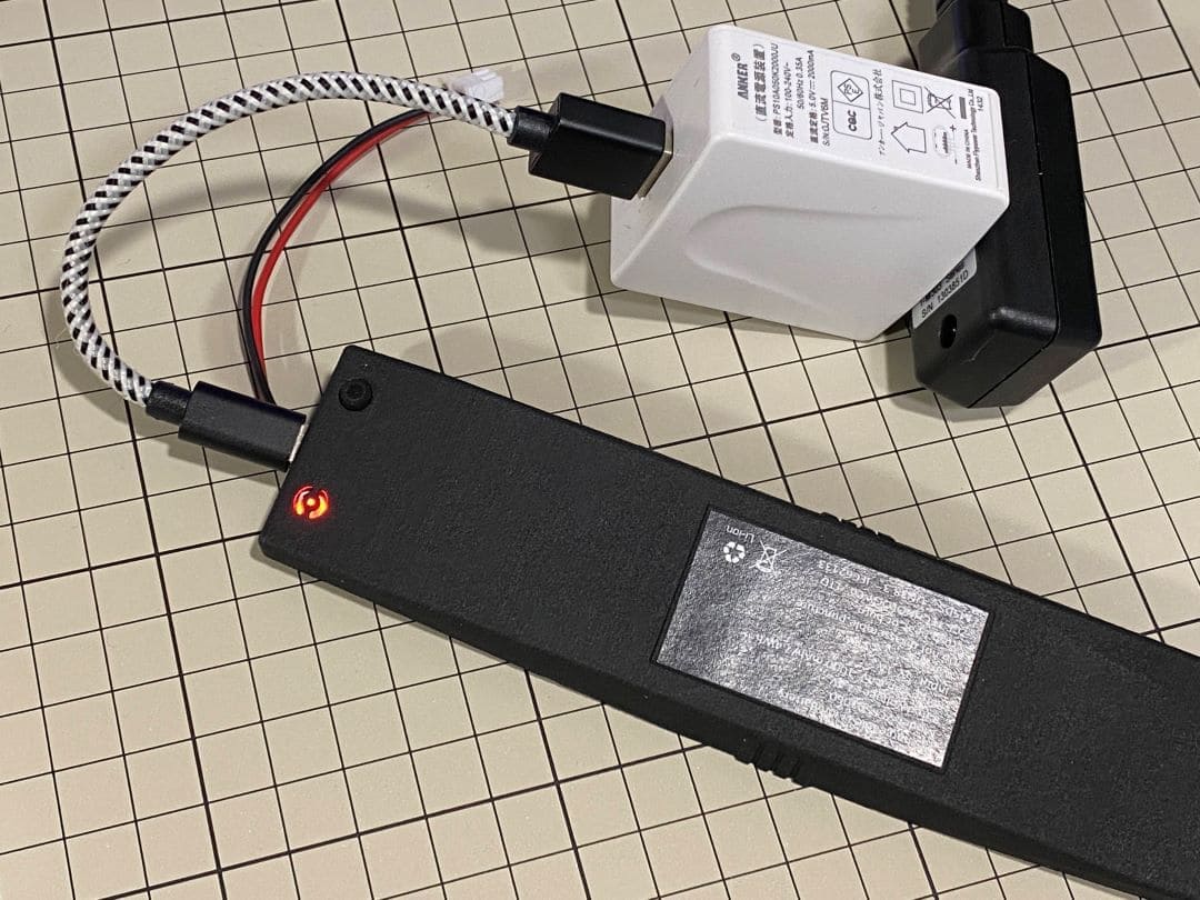
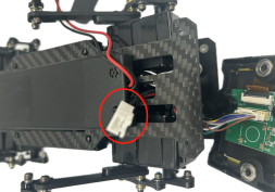
Step 1.1 Charging the battery
The battery is charged via USB, see picture for USB socket, and can also be charged while attached to the Mini Pupper body.
※ LED light: Green means there is enough power, and Red means you need to charge it.
※ We recommend 5V/1A adapter, if you use 5V/2A adapter, the battery IC will change it to 1A. It needs about 1 hour to charge 80% and the light will become green, and an additional 1 hour to 100%, anyway, you can use it when the light becomes green.
Step 1.2 Download the image
You can download the pre-built image files from Mini Pupper pre-built images
※ “xxx_stanford**.img” means the image is for Ubuntu 22.04 version.
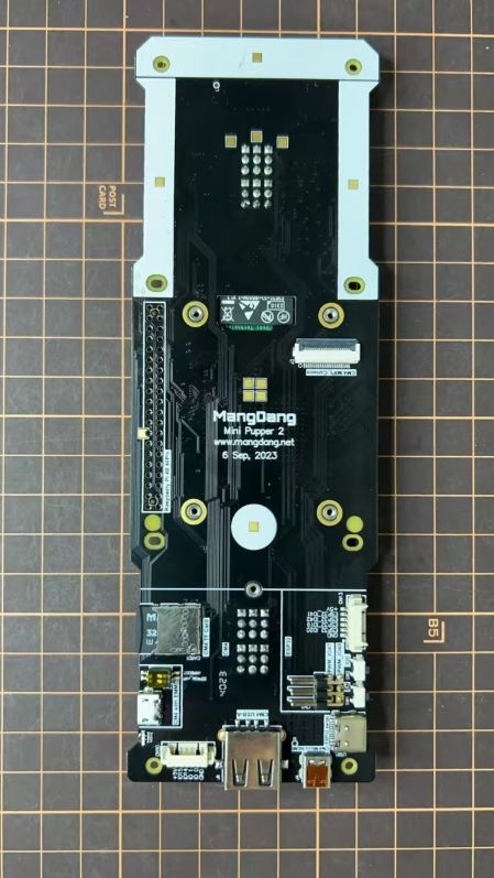
The picture below is the custom carry board.
Step 1.3 Write the image into a microSD card
Insert the microSD card into your PC’s SD card reader and write the image. We recommend the image creation tool balenaEtcher or Win32DiskImager as it is easy and reliable. It may take a while to complete.
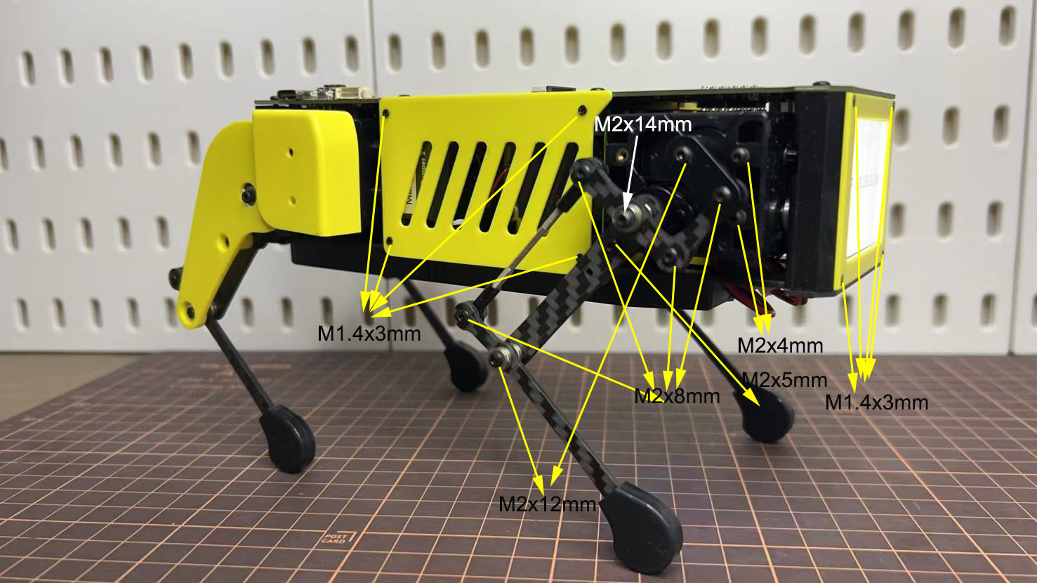
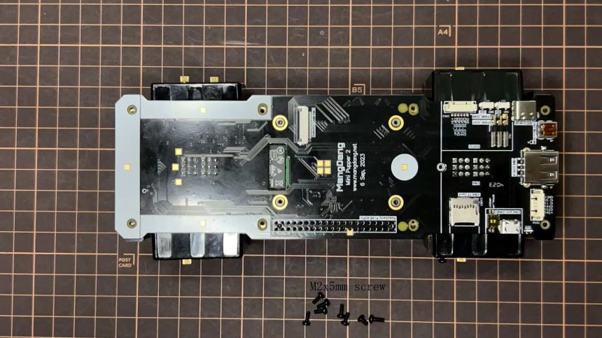
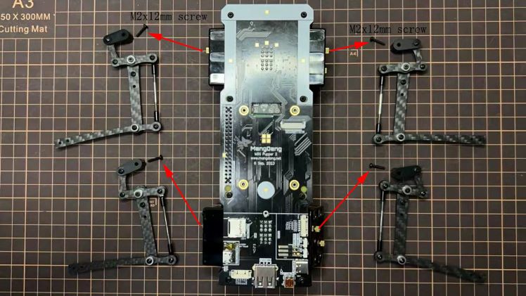
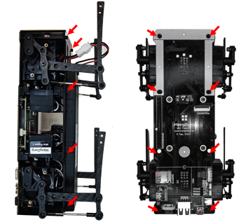
2. Position of the screws
The pictures show the position of the screws briefly.
3. Legs Assembly
Please refer to the below video clip.
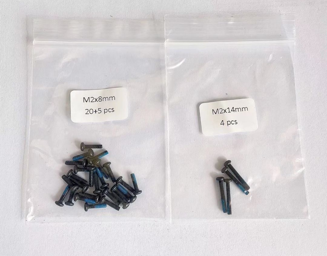
Bolt to use
M2x5mm 2x4=8 ①+②, ⑤+⑥
M2x8mm 3x4=12 ②+③, ④+⑦, ③+④
M2x12mm 1x4=4 ⑤+⑦
M2x14mm 1x4=4 ③+⑤
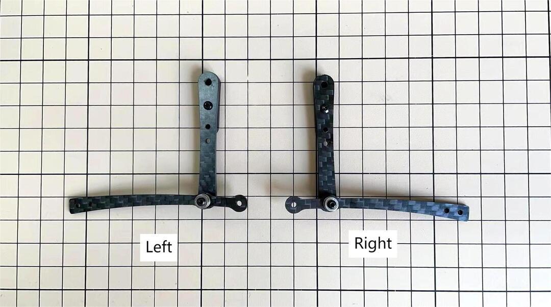
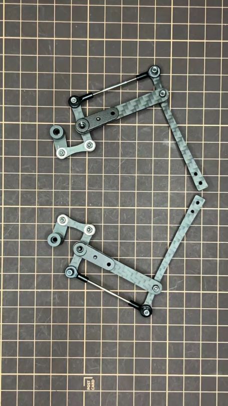
Step 3.1 Single leg
Assemble the four legs. The front and back of the right side are the same, and so are the front and back of the left side. Show you how to assemble the right side.
Video Instructions, please refer to the link https://youtu.be/Ut7UnS3CTZs
The parts are numbered as follows to explain.
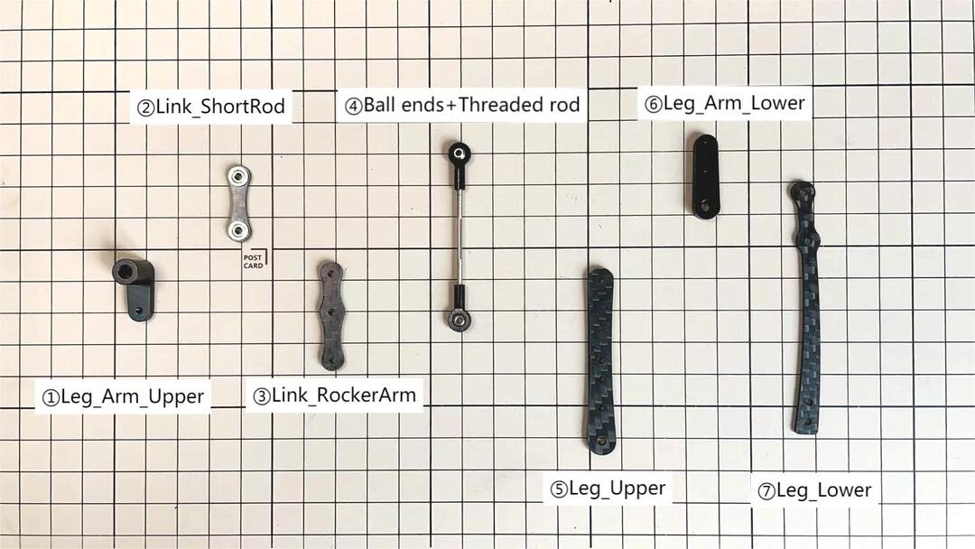
Assemble ① and ②
The two sides of bearings inside ② are different.
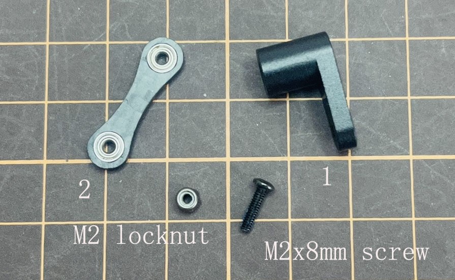
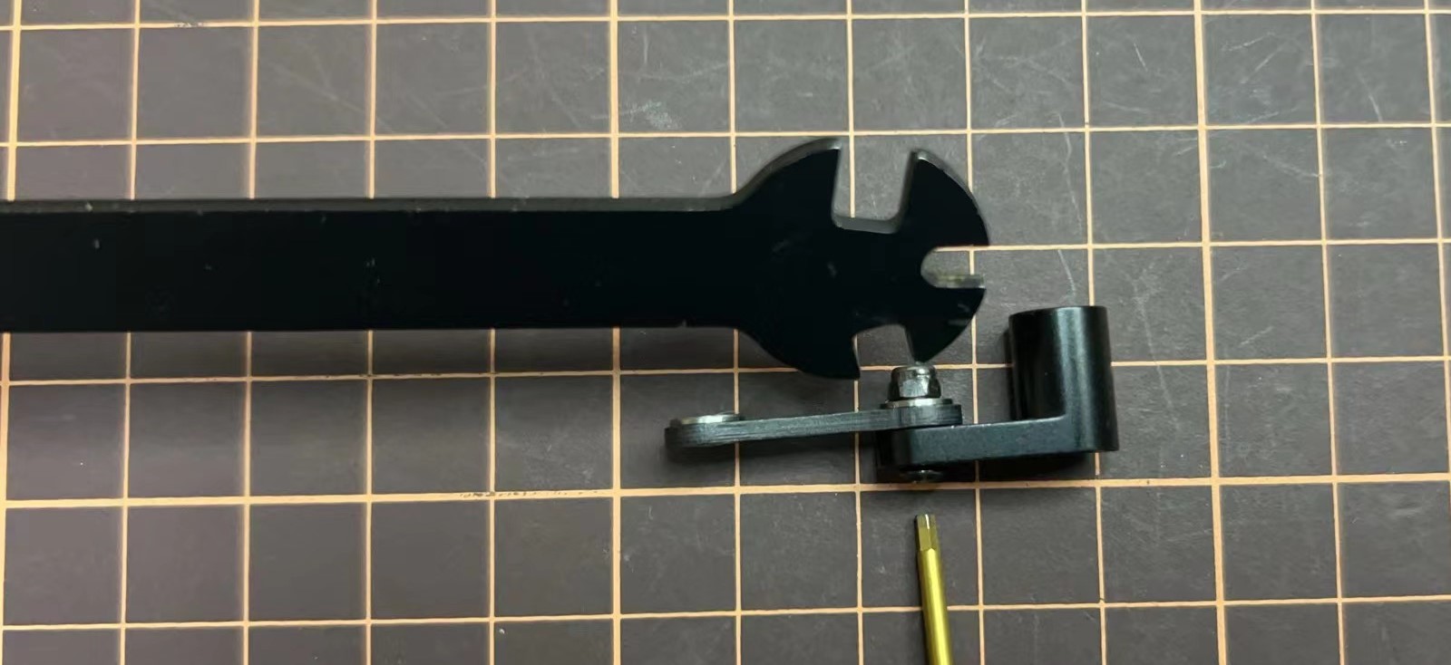
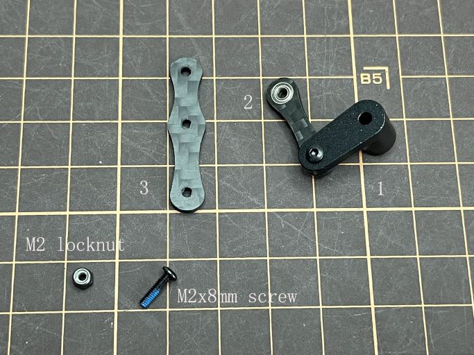
Assemble ② and ③
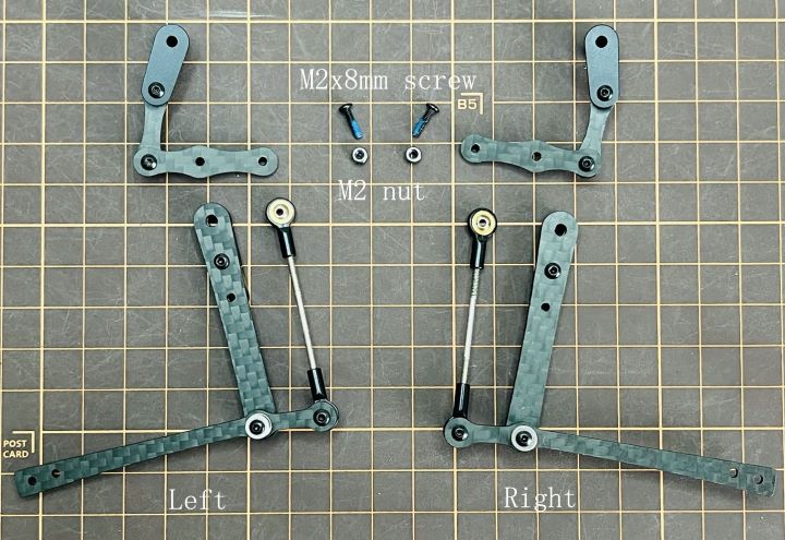
Use an M2x8mm screw and an M2 locknut. Insert the screw from the bottom to the top of ③, pass through ② and tighten with the nut. It is important to pay attention to the orientation of ③. Look carefully at the position of the hole in the middle.
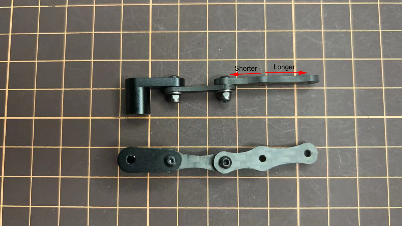
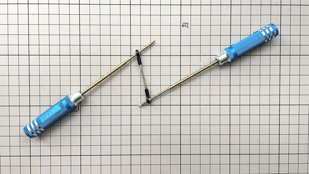
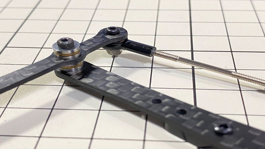
Adjustment of the length of ④
The length of ④ must match the length of ⑤. When adjusting the length, it is easier to use two long screws to make sure that the lengths match. Once the lengths have been adjusted, take apart all.
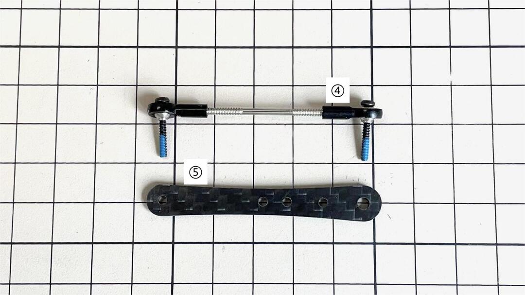
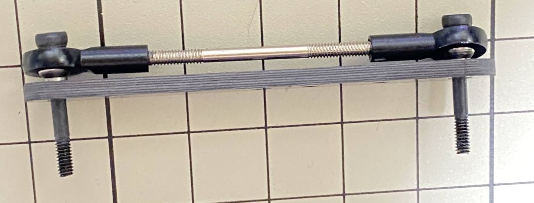
If it’s hard to twist, you can use two screwdrivers to assist.
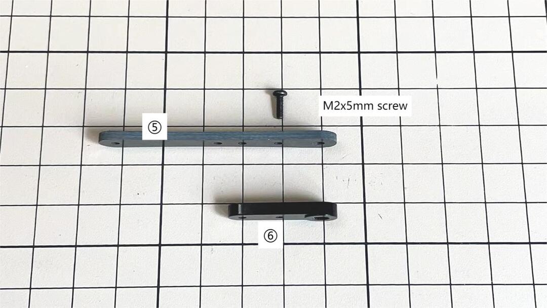
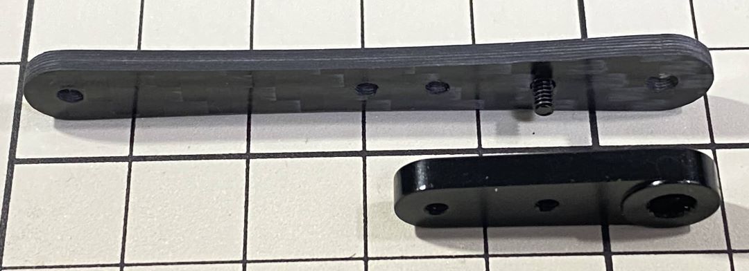
Assemble ⑤ and ⑥
Use one M2x5mm screw. Insert the screws into ⑤ first, insert them into the holes of ⑥, and tighten them. The large hole in ⑥ should be facing the surface.
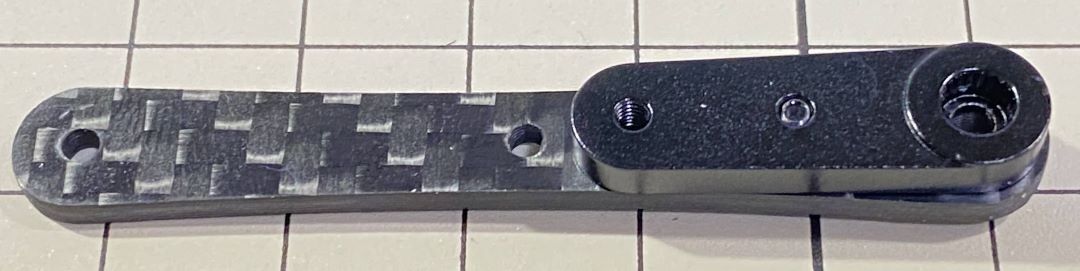
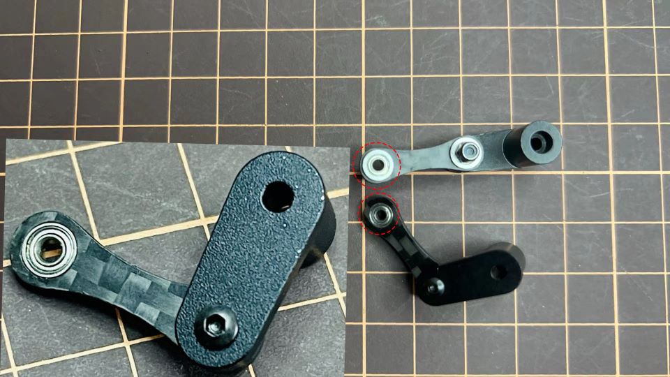
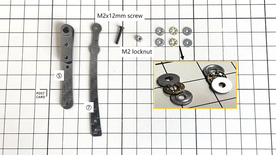
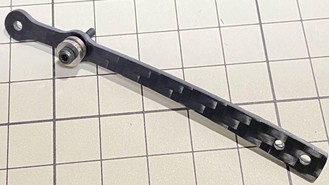
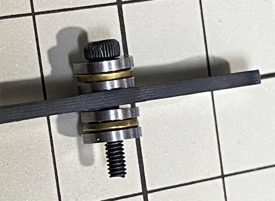
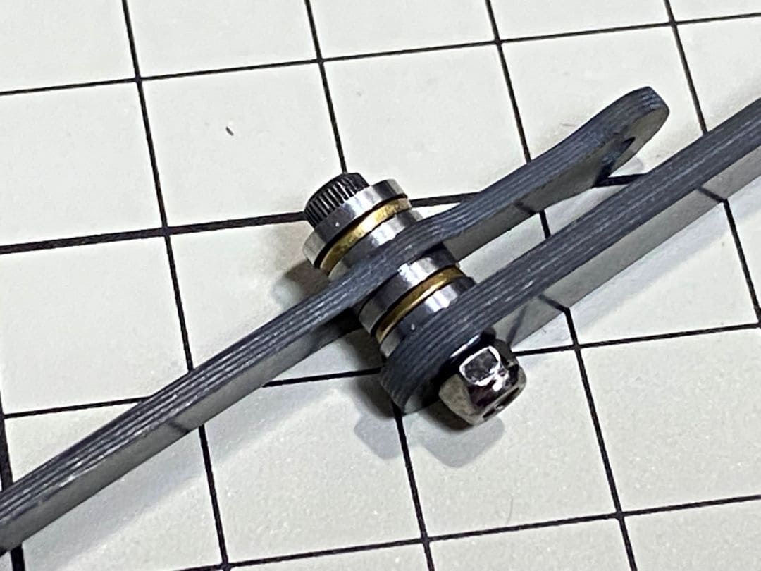
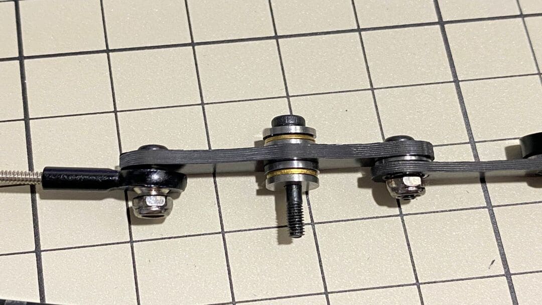
Assemble ⑤ and ⑦
Use an M2x12mm screw, an M2 locknut and two sets of ball bearings. Each ball bearing is made up of three parts, the top and bottom parts with the grooved side facing inwards. Insert a screw into a set of ball bearing. Then insert the screw into the hole ⑦. Taking care to look at the warped side of ⑦ to make sure it is facing the right way. Now screw in the another set of ball bearing. Finally, insert screw into ⑤ and tighten it with the nut.
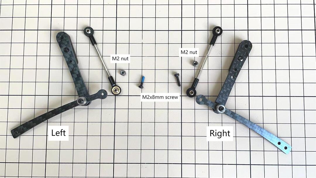
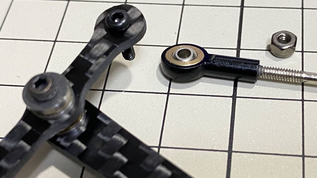
Assemble ④ and ⑦
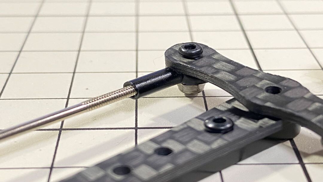
Use an M2x8mm screw and an M2 nut. Insert the screw into ⑦ and put ④ through, then tighten it with the nut. The direction of the front and back of ④ can be either.
Left and right leg
Assemble ③ and ④
Use an M2x8mm screw and an M2 nut. Insert the screw into ③ and put ④ through, then tighten it with the nut.
Left and right leg
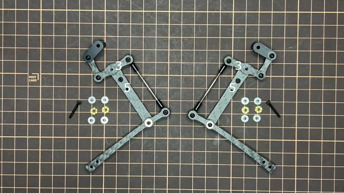
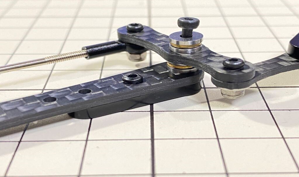
Assemble ③ and ⑤
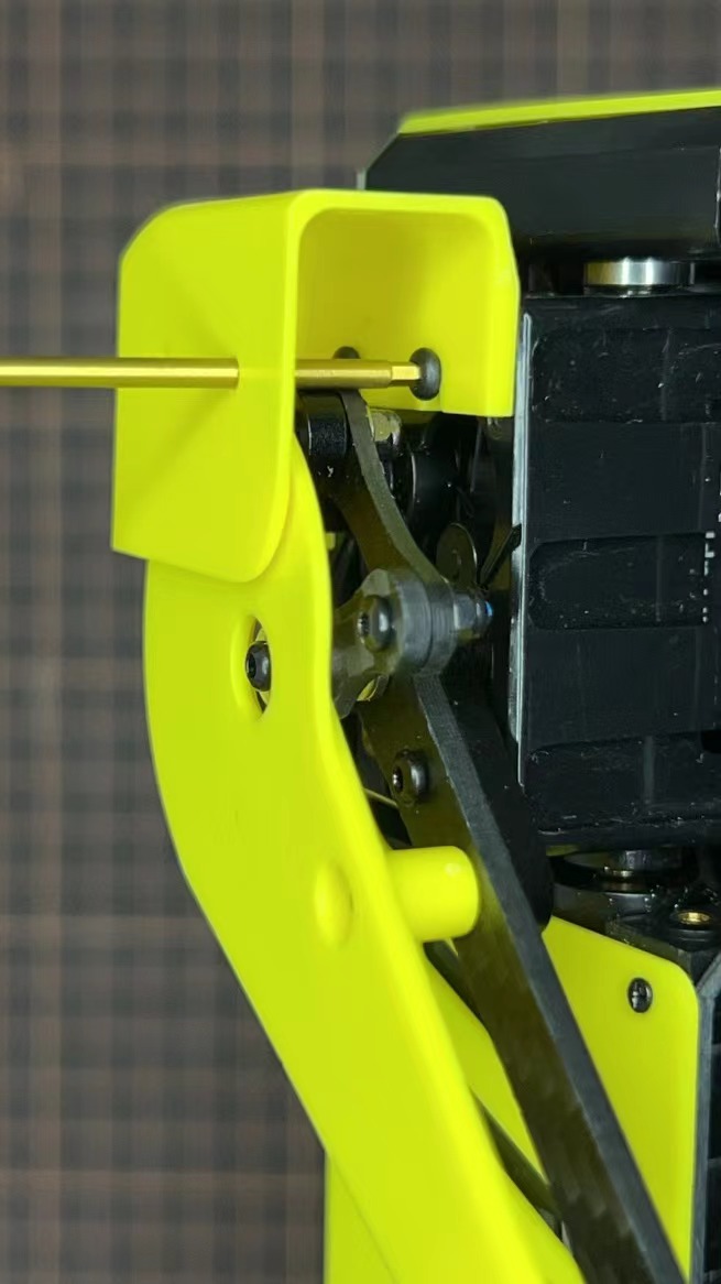
Use M2x14mm screws and two sets of ball bearings. Thread the screws through the bearings, ③, bearings, ⑤, in that order. The screws are not fixed, but you will tighten them when you mount the servo in the next step.
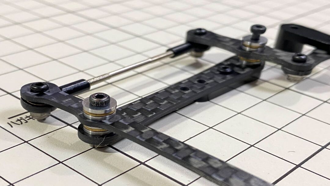
Completion of a right leg
Now we have one leg on the right side. Here are some pictures so you can see it from different angles. The left leg should be symmetrical with the right one.
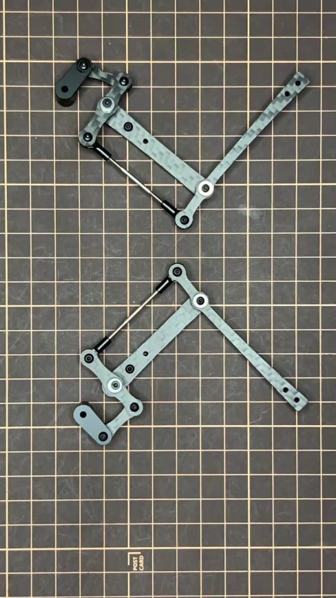
opposite side
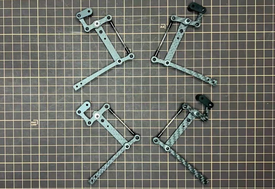
Step 3.2 Four legs
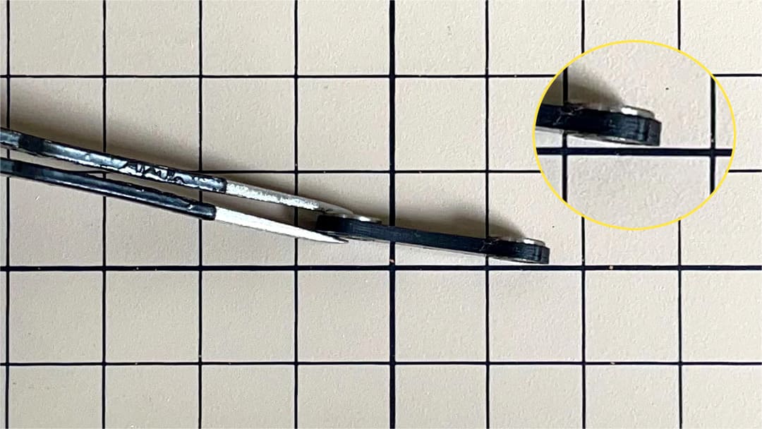
Step 3.3 Locktite
After Mini Pupper run sometime, some screws or nuts will loose, you have to check and tighten them if needed. It’s helpful to understand how it works.
※ We don’t recommend new users to use the Loctite at first, you can use it after you have much background.
※ Loctite prevents the nut from loosening, but it is not essential, as it can be tightened only when looseness is noticed.
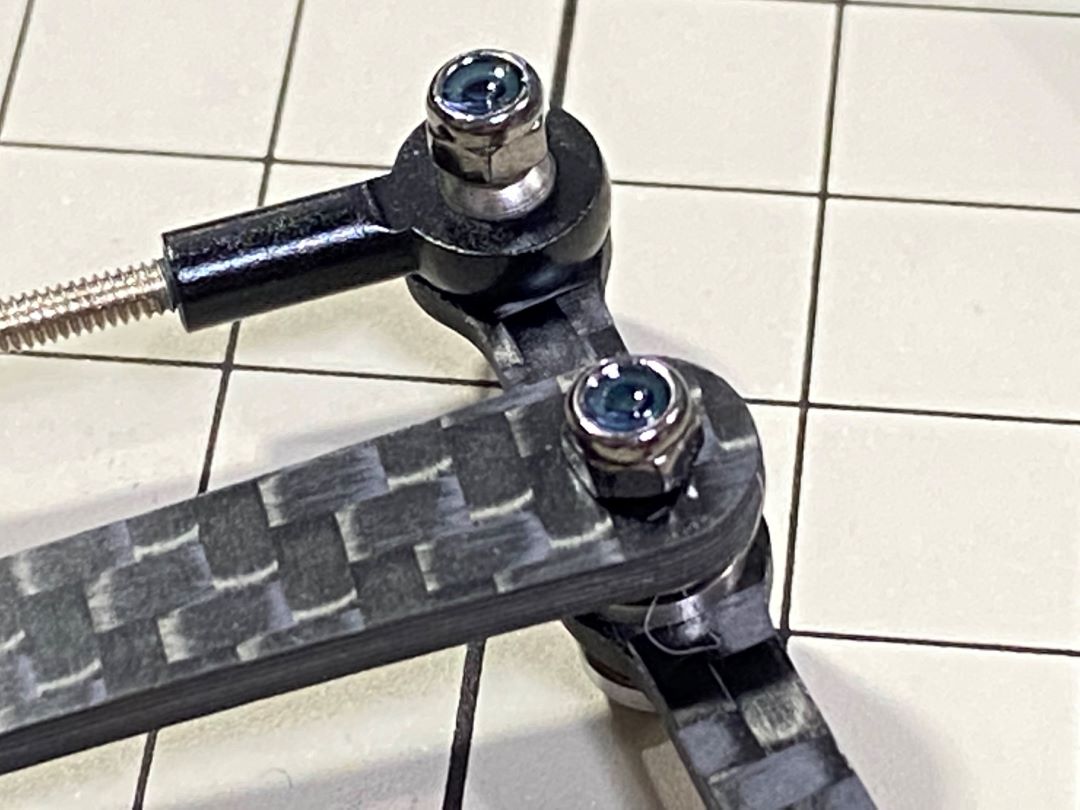
Some screws are also secured with glue as the below picture shows.
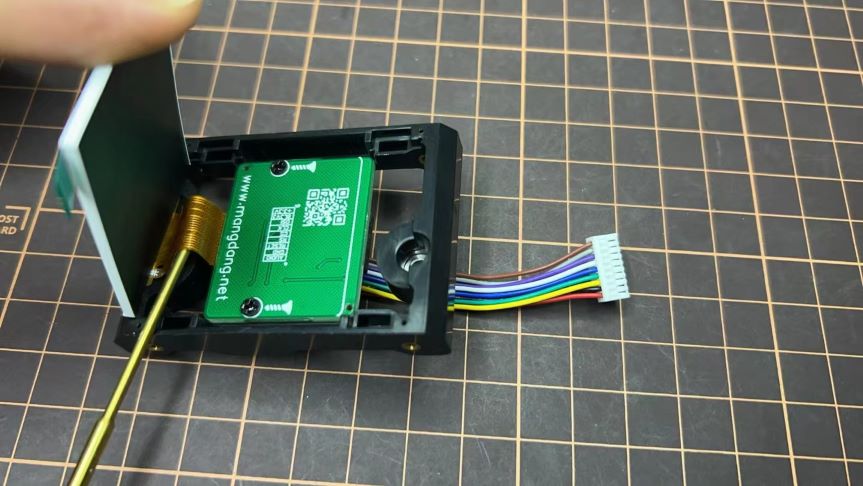
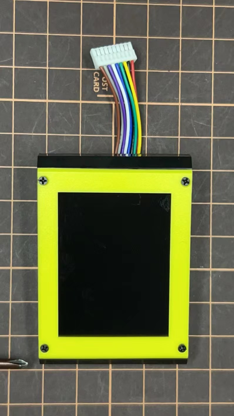
4. Display and Frame of face
Remove the protective sheet for the display. Fold the thin flexible cable at the edge of the display. Attach the board and the display to the main unit.
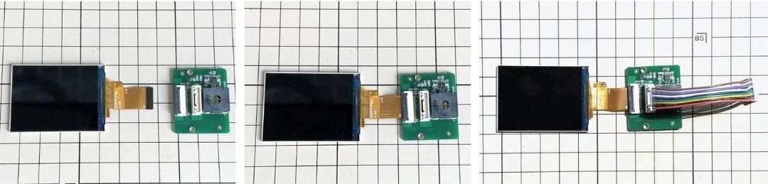
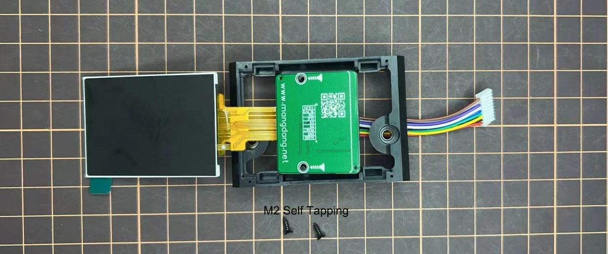
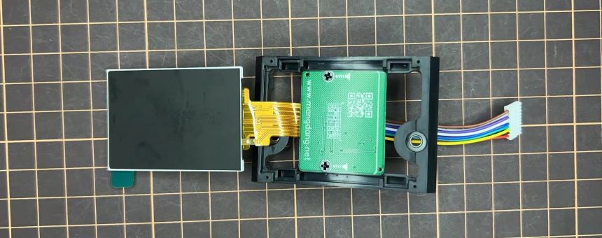
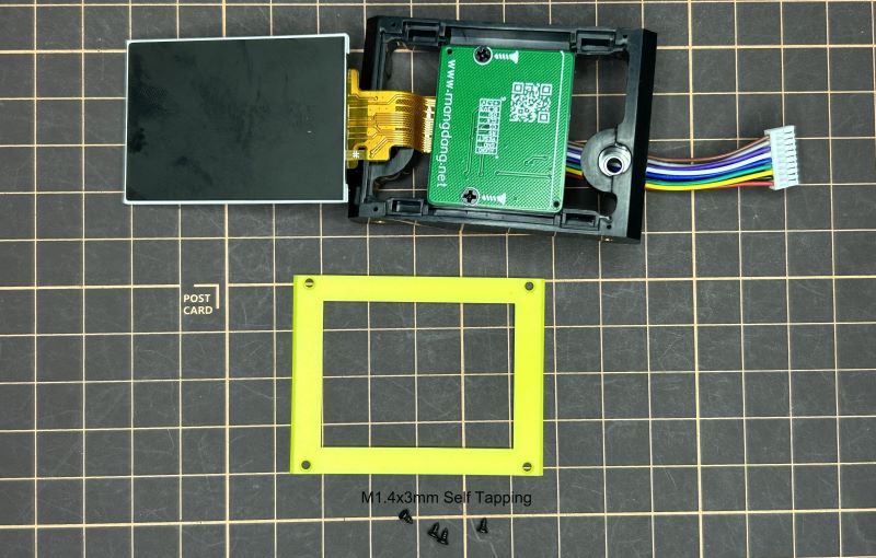
When attaching the display, you can use a stick to gently push the flexible FPC cable, so that it goes as far back as possible. Don’t bend this FPC cable at 180 degrees.
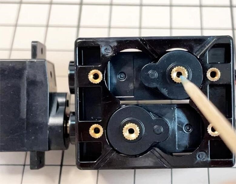
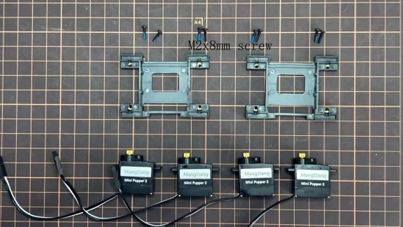
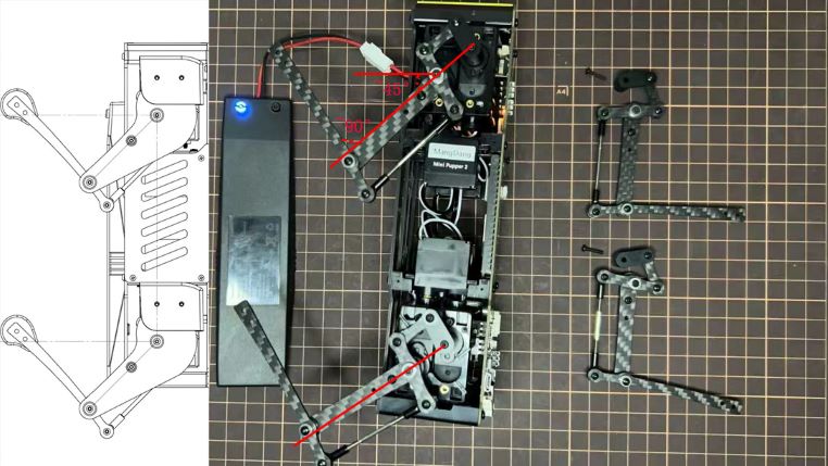
5. Body Frame and Hips Assembly
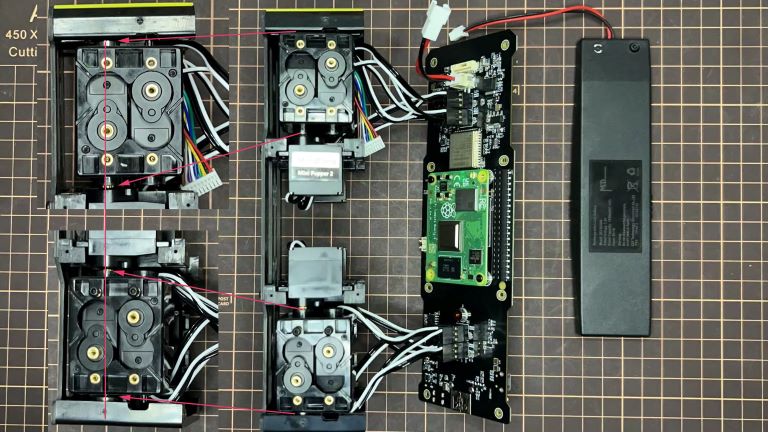
Refer to the top video for how to set servo ID.
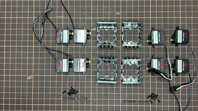
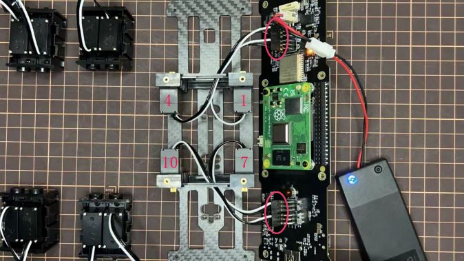
For the position of each servo, please refer to the below picture.
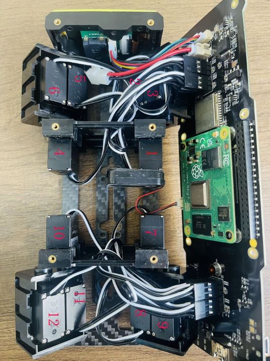
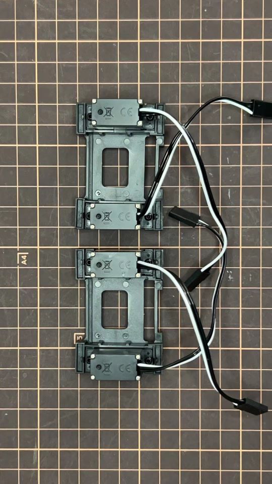
Step 5.1 Body center parts
Connect the No.1, 4, 7, 10 servos to the body center parts.
It is useful to put masking tape on the cables and write the number of servos during this process to make it easier later.
Pay attention to the center part direction.

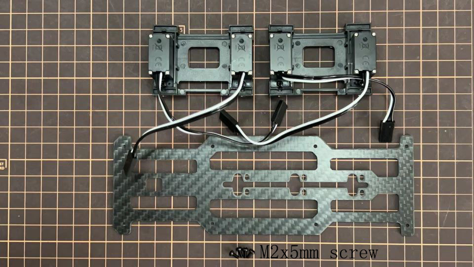
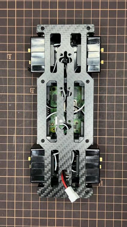
Connect the center parts to the bottom carbon fiber
Be careful of the carbon fiber front and rear orientation.
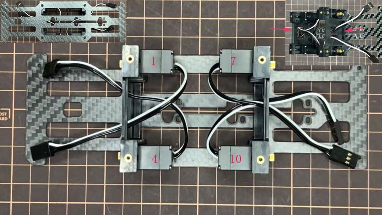
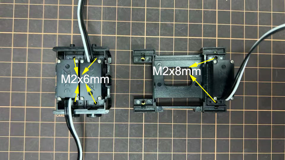
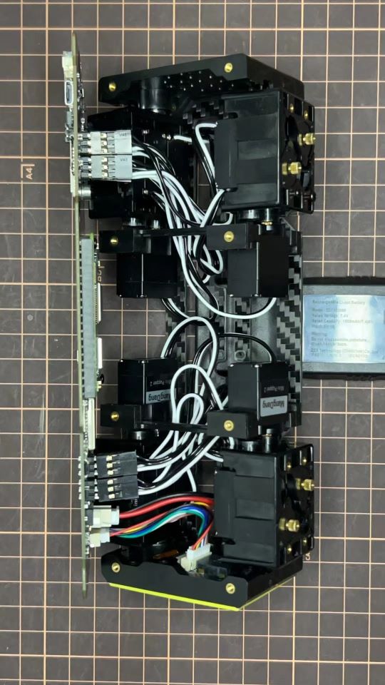
Step 5.2 Hip parts
Assemble four hip parts, please refer to the servo positions.
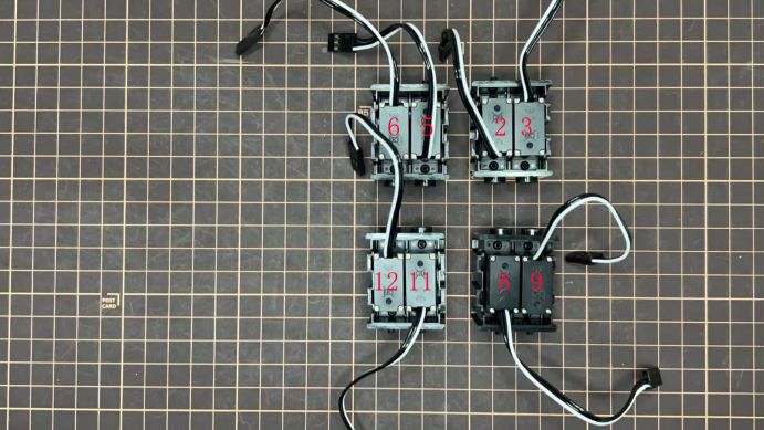
Ensure the No.1, 4, 7, 10 servos at the right position.
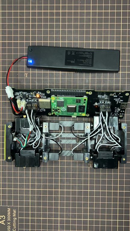
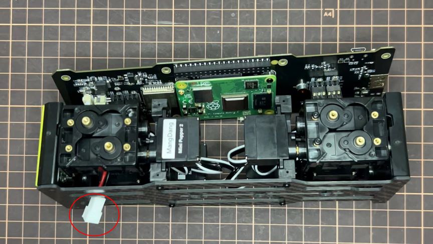
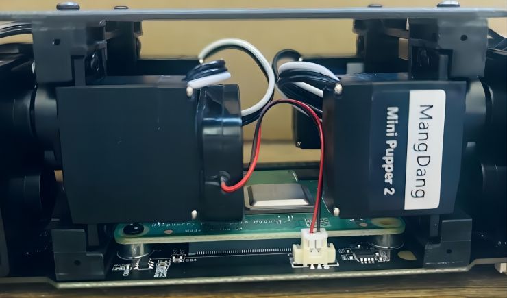
Use the custom cable to connect the battery to the top PCB board, and click the battery button for more than 3 seconds to boot up it.
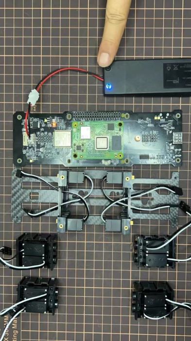
Connect the servos to the top PCB board, please pay attention to the servo connector directions.
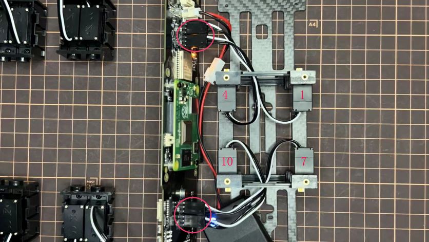
Connect the four hip parts to the body, please pay attention.
Don’t power off the battery now.
Ensure all the servo positions are right.
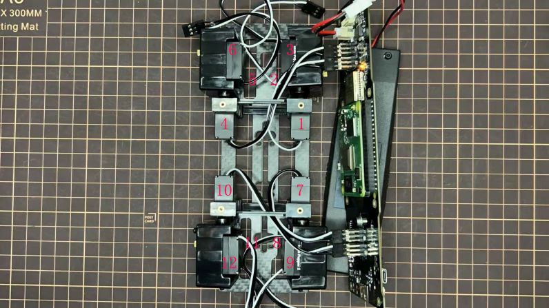
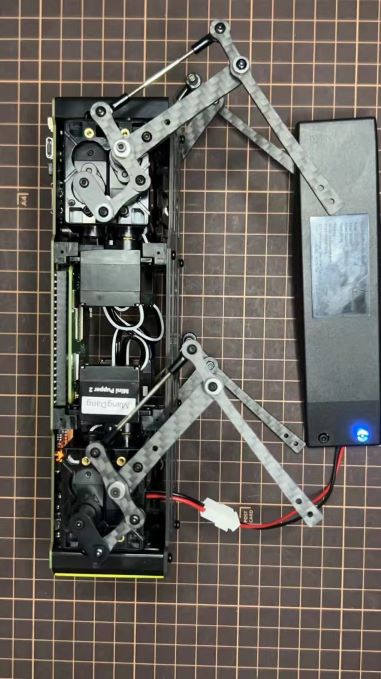
Step 5.3 Front and back body parts
Power off the battery, and connect the front and back body parts.
Pay attention to the directions.
Power on the battery to check the hip parts all at their right positions, connect all the rest servos to the PCB board, and then power off the battery and go ahead.
Connect the LCD cable to the PCB board, make the servo cables clear.
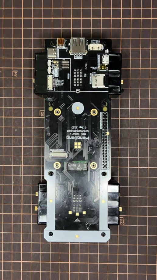
Fix the top and bottom boards.
Step 5.4 Assemble four legs to the body
Pay attention to the theoretically best angles, it’s better to meet the theoretically best angles as much as possible. But don’t worry, we’ll use the software to calibrate the angles later.
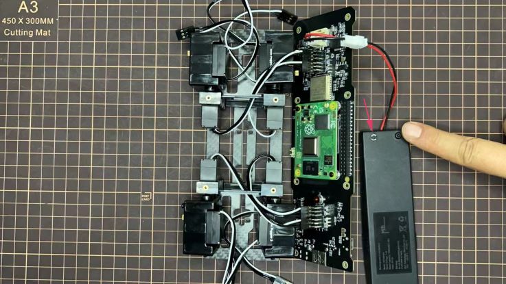
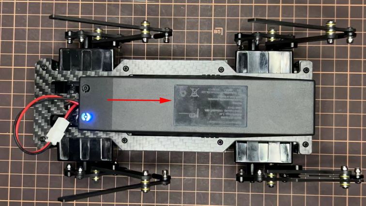
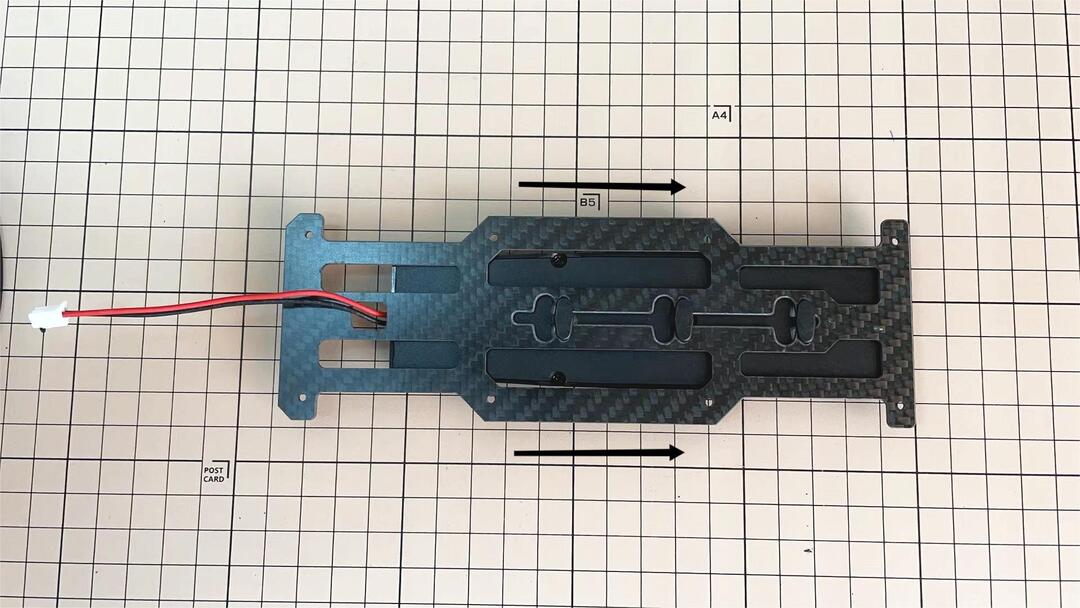
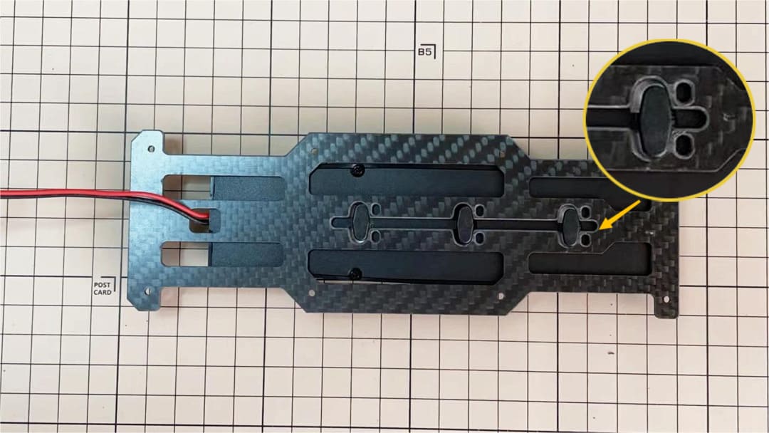
Step 5.5 Assemble the battery to the body
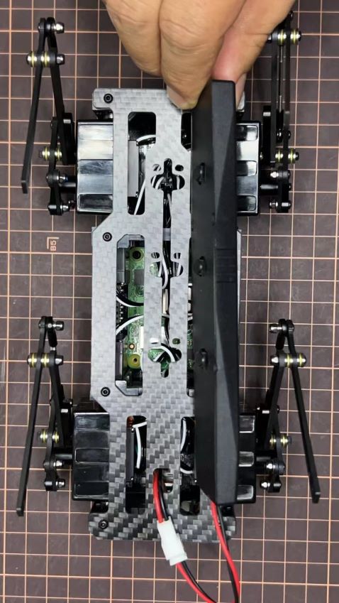
Slide the battery backward and secure it.
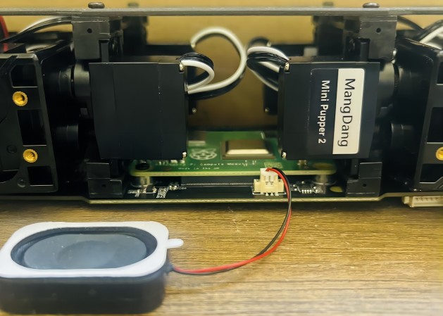
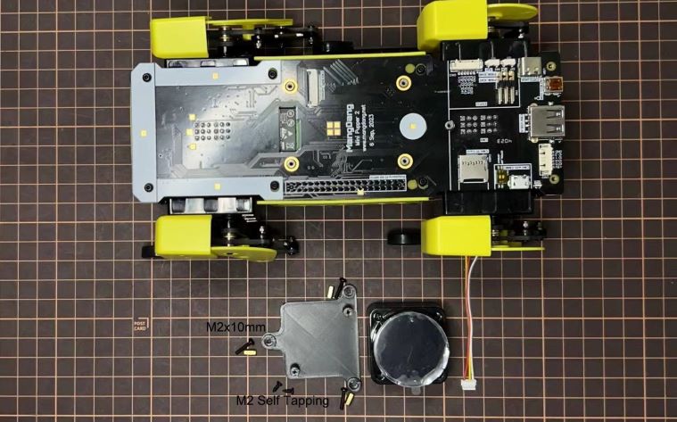
Step 5.6 Assemble the speaker
6. Standard Kit Main Parts Assembly
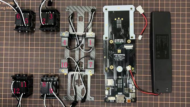
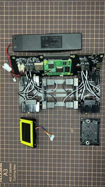
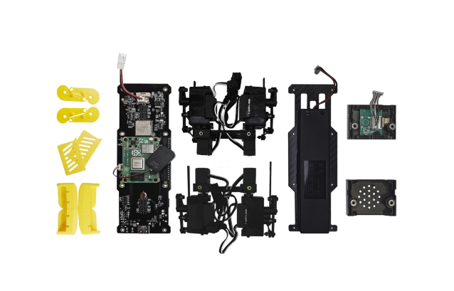
Step 1 Preparation
The following picture shows all the parts.
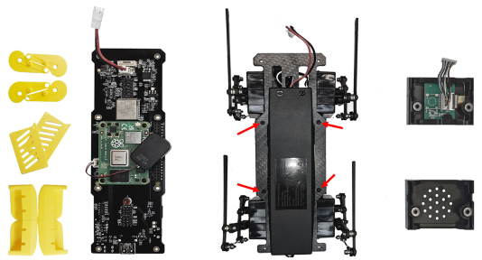
Step 2 Assemble the bottom plate.
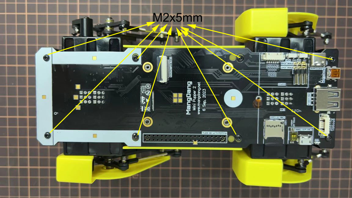
Connect the 4 legs to the bottom plate using the M2 x 5mm screws.
Step 3 Assemble the top PCB board.
Insert the four-legged connection wire into the top board. Connect the LCD screen cable to the PCB board. Please pay attention to the direction.
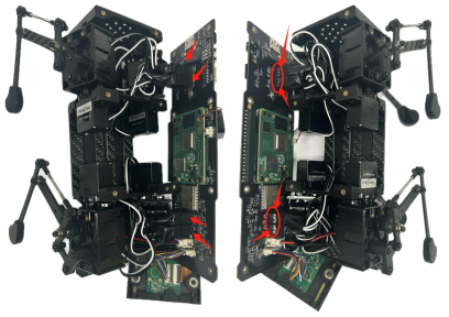
Step 4 Adjust the power line
Pass the power line on the PCB board through the hole in the bottom plate.
Step 5 Assemble the speaker
Fix the PCB board and bottom board using M2 x 5mm screws.
7. Cover Assembly
Please refer to the below video clip.
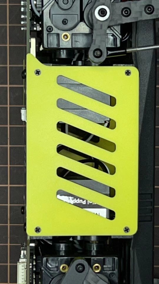
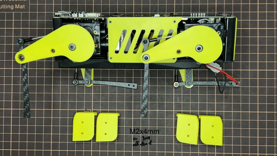
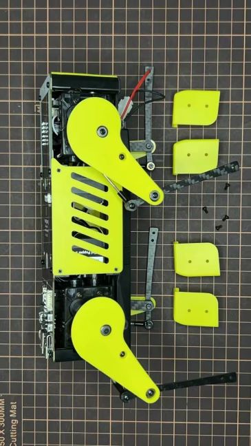
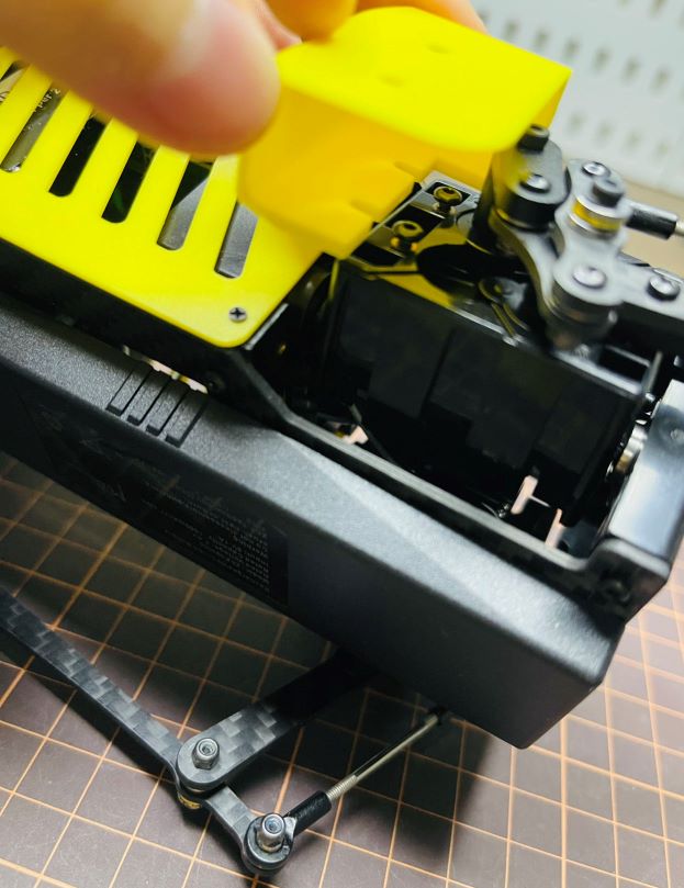
Step 1 Side panels
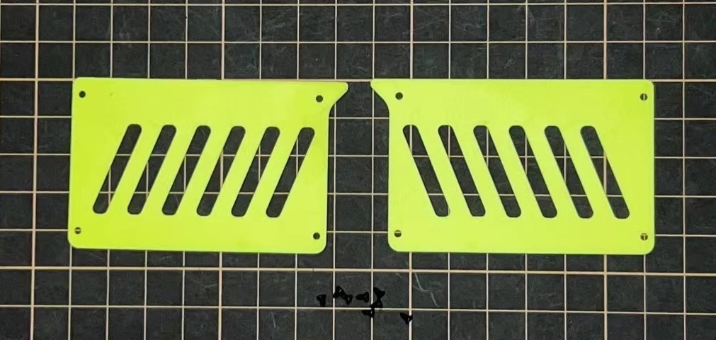
Step 2 Shin guards
Use four M2x10mm countersunk screws.
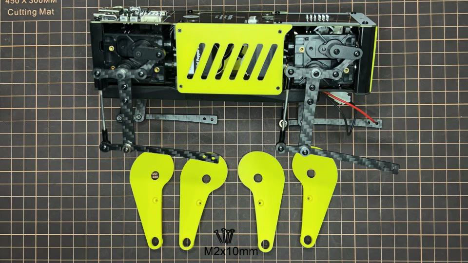
Step 3 Shoulders
Insert only the screws first and then insert the shoulder parts into the gap. Insert the 2 mm hex driver into the hole in the shoulder part and tighten the screws.
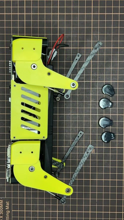
Step 4 Shoes
Put on 4 shoes.
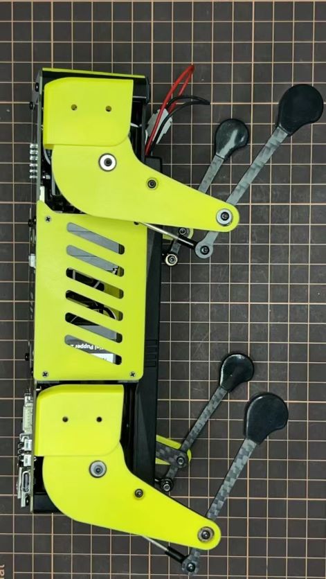
Complete!
8. Add-On Assembly
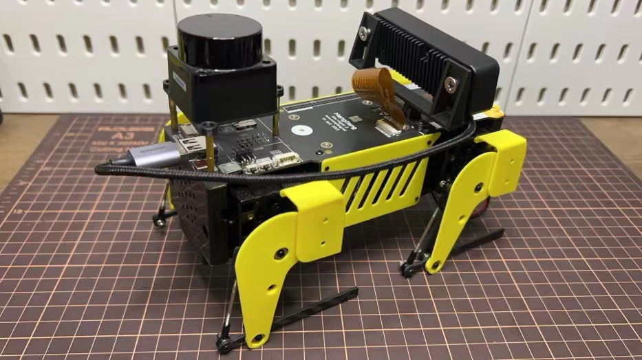
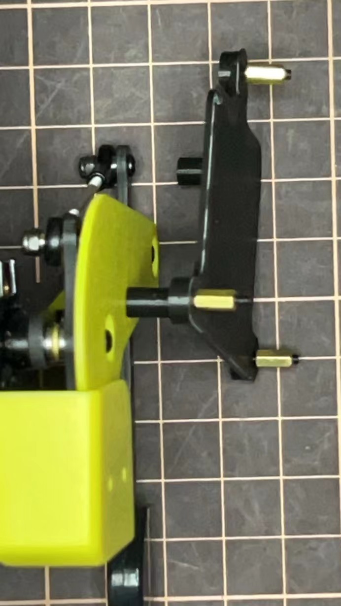
Step 1 Lidar
If you order the Lidar, the 3D-printed Lidar holder and custom cable will be shipped together. You can also print the holder by yourself using the STL files
Connect the 3 holders to the 3D-printed part.
Connect the custom cable to the Lidar connector on the PCB board.
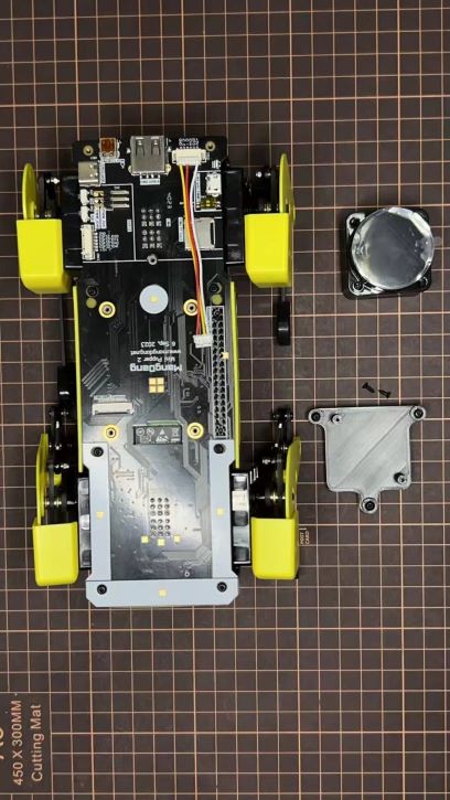
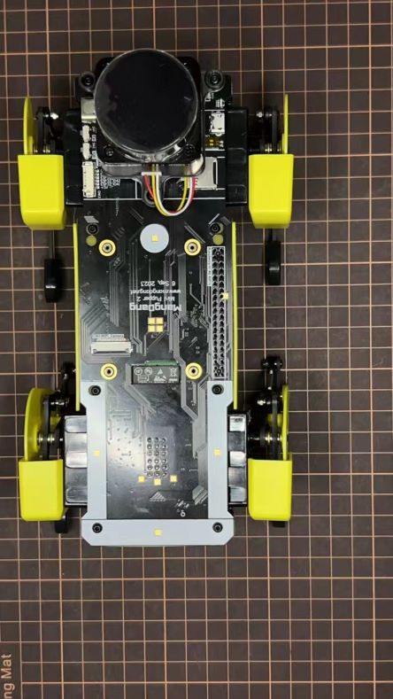
Fix the 3D-printed part on the PCB board.
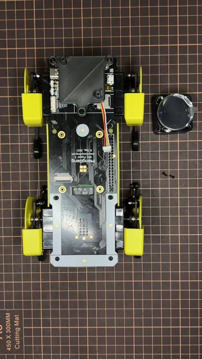
Connect the custom cable to the Lidar module and fix it using the self-tapping screws.
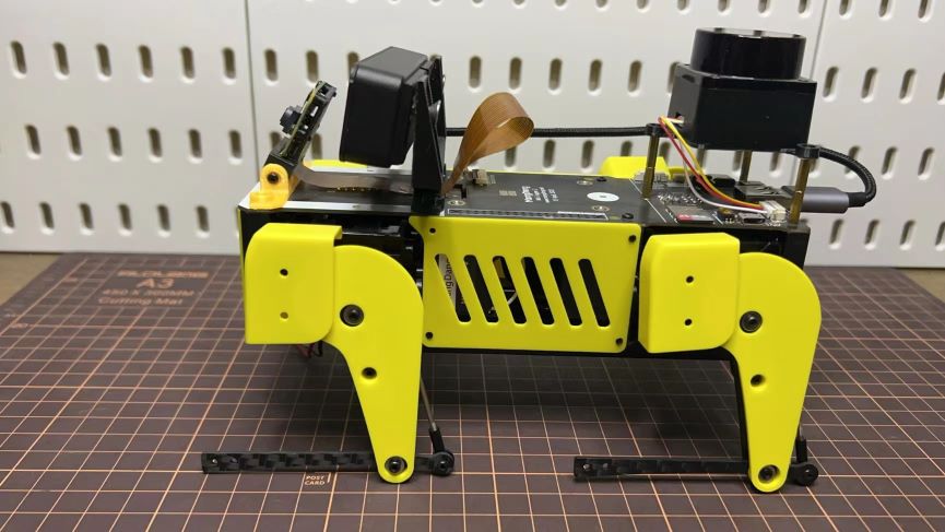
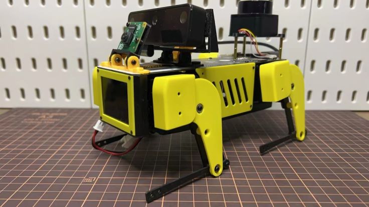
Step 2 Camera
Mini Pupper 2 also supports the single Pi camera or OpenCV OAK-D-Lite camera module. You can also print the holder by yourself using the STL files